How To Design A Progressive Stamping Die For Efficiency And Accuracy
April 10th, 2026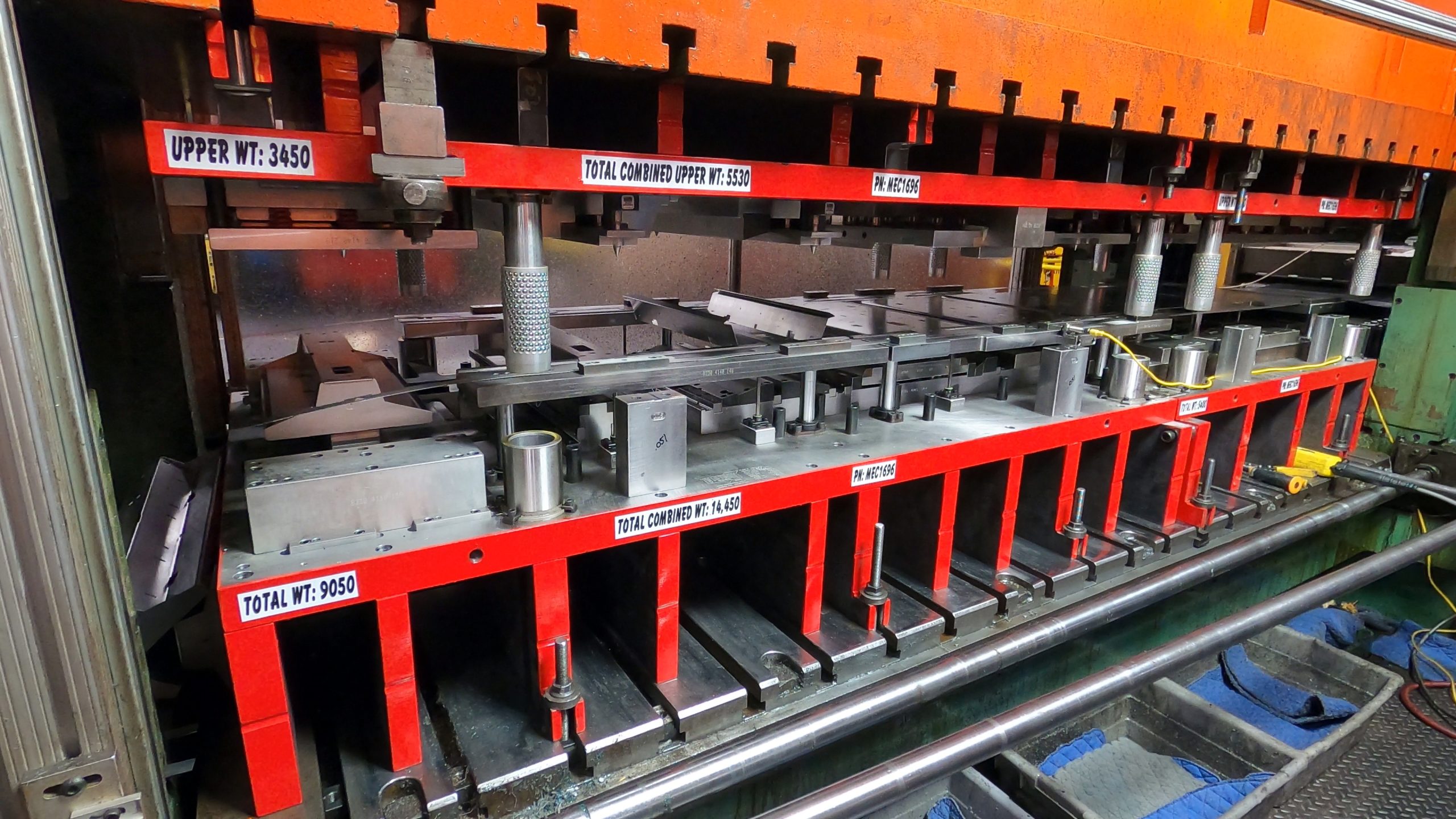
A progressive die does not begin with steel. It begins with decisions made in the design phase that shape cost, accuracy, and long-term production performance. The path from flat strip to finished part depends on how well the die anticipates material movement, feeding behavior, springback, and tool interaction at every station. Small design choices affect strip stability, die life, and part quality across millions of cycles.
This article examines progressive stamping die design from a practical engineering viewpoint and explains how thoughtful planning leads to faster production, tighter tolerances, and lower scrap.
Understanding Progressive Stamping Die Design from the Start
Progressive stamping die design is the structured planning of how a sheet metal strip will move through multiple stations, with each stroke performing a defined operation. Piercing, forming, bending, drawing, and cutting occur in sequence while the part remains attached to a carrier strip until the final station.
This method allows progressive die stamping to produce complex parts at high speeds with consistent repeatability. Accuracy depends less on the press and more on how well the die controls strip position, material behavior, and tool alignment throughout the sequence.
The designer must think in terms of motion, not only geometry. The strip feeds forward one pitch at a time. Pilots register location. Lifters raise the strip. Strippers control material during punch withdrawal. Every component works together as a timed mechanical system.
Strip Layout and Sequence Planning Drive Everything
Strip layout represents the foundation of progressive stamping die design. It defines:
- Part orientation on the strip
- Order of operations
- Pitch distance between stations
- Carrier type and width
- Material utilization and scrap pattern
A poorly planned strip layout increases scrap, causes uneven forces, and leads to die wear or strip tipping. A well-planned layout distributes forming forces evenly and allows the strip to feed smoothly through the die.
The sequence of operations also matters. Piercing and notching usually occur early while the material remains flat. Forming and bending follow after the profile takes shape. This prevents distortion of holes and features during later operations. That said sometimes piercing must be done post forming to accommodate tolerance considerations of features.
In many sample stamping trials, engineers revise strip layouts several times before production tooling begins. These iterations expose feeding problems, grain direction issues, and force imbalance that only appear during testing.
Grain Direction and Part Orientation Affect Forming Accuracy
Sheet metal has grain direction from rolling. Forming with the grain can cause cracking, fatigue, or inconsistent bends. Rotating the part at an angle to the grain often improves durability and dimensional control, especially when tight tolerances are required.
This choice may increase material waste, but it improves part reliability. In high-volume progressive die stamping, fewer cracked parts and reduced tool stress offset the added scrap.
Part orientation also affects feed length. Shorter feed distances allow smoother strip movement, especially with thick materials and narrow strips.
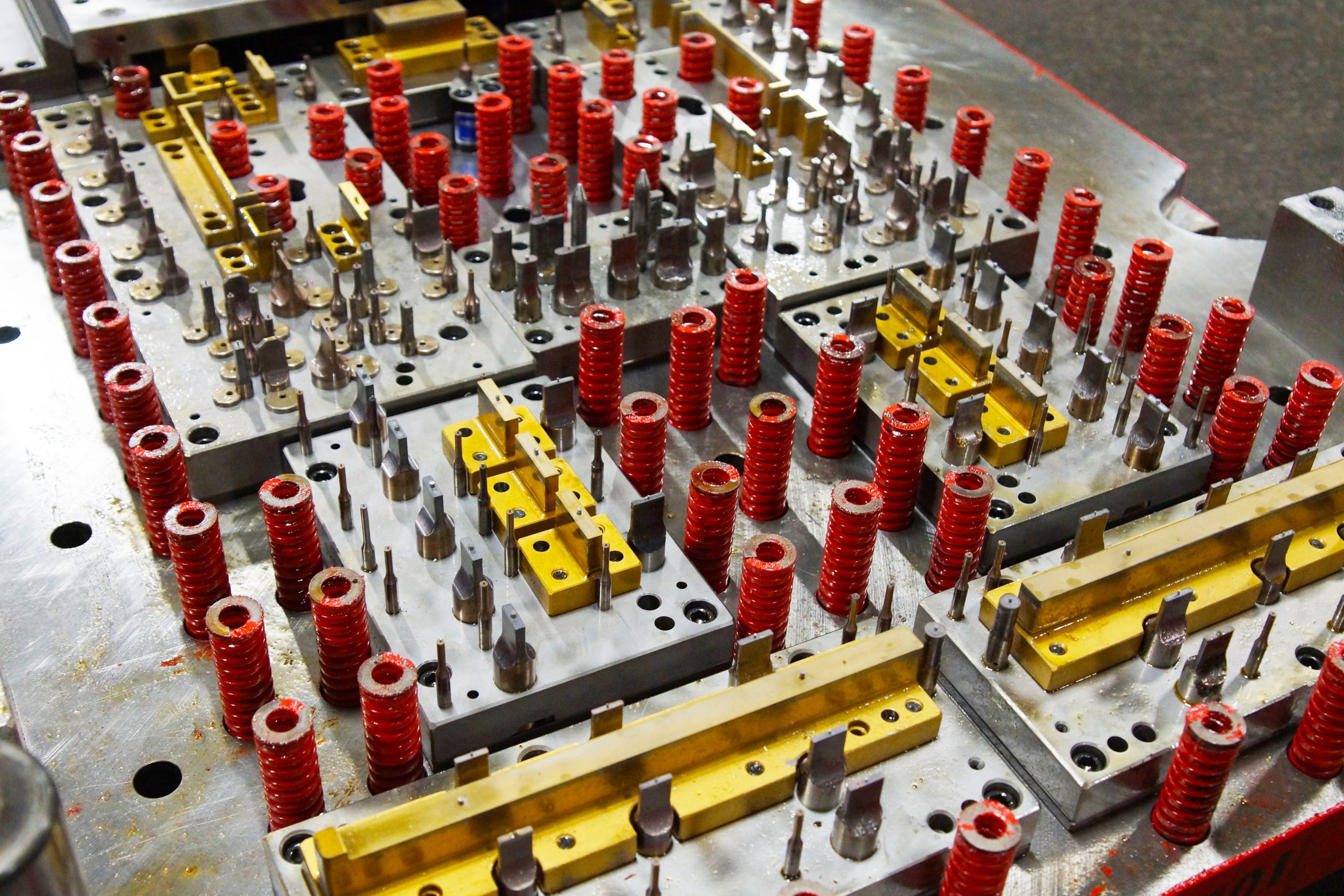
Carrier Design Controls Strip Stability
The carrier, also called webs or ties, transports the part from station to station. Its design affects feeding stability, alignment, and scrap rate.
General carrier guidelines include:
- Width at least twice the material thickness
- Length that allows stretch and bending during forming
- Attachment points that allow easy removal and burr control
- Consistent carrier lengths if multiple carriers exist
Several carrier types serve different purposes:
Center Carriers
Located near the center of the part. Narrow center carriers allow forming around the part. Wide carriers limit forming to the sides but reduce scrap.
Inboard Carriers
Attached at two points, one near the center and one near the edge. This design balances strip movement.
Lance Carriers
Created by lancing instead of trimming. Scrap decreases but shaving may occur.
Outside Carriers
Attached outside the part profile. These allow forming near the center and often use lifter rails for balance.
One-Sided Carriers
Attached to only one side. This gives access for forming on three sides but may cause strip movement and alignment challenges.
Feed Height and Strip Lifting Influence Speed
After each stroke, the strip must lift slightly to break the oil seal and advance to the next station. Excessive lift slows production and increases vibration, which can misalign the strip.
Designers aim for minimal lift while maintaining clearance for formed features. Sagging between lifters can buckle carriers, especially with thin materials. Bar lifters that span between parts help maintain strip flatness.
Lower lift height leads to faster cycle times and more stable feeding in progressive die stamping.
Pilots Maintain Registration and Accuracy
Pilots align the strip before each operation. Without them, minor feeding errors accumulate and create tolerance drift across stations.
Pilots often enter holes pierced in early stations. However, if these holes require tight tolerances, using them as pilots may elongate them. In such cases, separate pilot holes on the carrier maintain accuracy.
When two sets of pilots are required, punching them simultaneously improves alignment.
Accurate piloting allows progressive stamping die design to maintain repeatability across long production runs.
Tooling Clearance and Material Behavior
Cutting clearance between punch and die opening affects edge quality and tool wear. Too little clearance increases force and dulls tooling. Too much clearance creates burrs and tapered edges.
Clearance depends on material type and thickness. Stainless steel stamping and aluminum stamping require different values due to ductility and hardness differences.
Springback also affects forming geometry. Designers intentionally over-bend parts in the die to compensate for material recovery after forming.
These factors become visible during sample stamping and early trials before full production begins.
Stripper Plates, Lifters, and Stock Guides Work Together
After a punch forms or pierces material, the strip tends to stick to the punch. The stripper plate holds the strip flat and removes it from the punch during retraction.
Lifters raise the strip slightly for advancement. Stock guides keep the strip centered during feeding. If these components lack proper spacing or alignment, the strip may twist or jam.
Their interaction forms the mechanical rhythm that allows smooth progressive die stamping at high speeds.
Die Set Alignment and Component Precision
The die set includes upper and lower shoes held in alignment by guide pins and bushings. Even slight misalignment can break punches or damage die inserts.
Punch holders secure the working components. Die blocks contain the cutting openings. These parts must maintain micron-level accuracy for long-term durability.
This precision allows progressive stamping die design to hold tight tolerances over millions of cycles.
Simulation and Digital Validation Reduce Risk
Modern die design uses simulation software to predict material flow, thinning, wrinkling, and springback before tool steel machining begins.
Engineers test multiple strip layouts digitally, optimize blank shapes for drawn parts, and adjust forming geometry virtually. This reduces trial-and-error during physical testing.
Digital validation shortens development time and leads to faster production readiness.
Design for Manufacturability Lowers Tooling Cost
Small part design changes reduce die complexity significantly:
- Larger bend radii reduce material stress
- Proper hole spacing prevents distortion near bends
- Reasonable tolerances avoid expensive tool steel and grinding processes
- Material selection affects forming behavior and tool wear
When designers consider these factors early, custom metal stamping services achieve better results with fewer adjustments later.
How Progressive Die Stamping Compares with Other Die Types
Progressive dies excel in high-volume production of complex parts. Each stroke produces a finished part while the strip advances.
Compound dies perform cutting operations in one station but lack forming capability. Transfer dies move individual parts between stations and suit large parts.
For small to medium components requiring multiple steps, progressive die stamping offers unmatched speed and repeatability.
Partner With Talan Products for High-Volume Progressive Die Stamping Solutions
At Talan Products, we apply decades of tool and die design knowledge to progressive die metal stamping, aluminum stamping and fabrication, stainless steel stamping, and fabricated aluminum extrusions. Our team focuses on strip stability, die longevity, and low PPM performance across high-volume production.
As an ISO 9001:2015 registered metal stamping partner with nearly 40 years of experience, we build tooling and processes that deliver accuracy, speed, and long-term value.
Connect with us to discuss your next project.
A Guide To Tool And Die Manufacturing
April 5th, 2026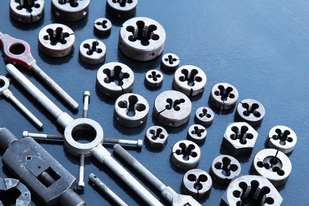
Metal parts used in vehicles, appliances, electronics, and medical devices often begin long before production lines activate. They begin in a tool room. The accuracy of each stamped component depends on how well the tool and die system was designed, machined, fitted, and tested. A slight flaw at this stage can echo through thousands of parts later.
Tool and die work shapes how metal flows, bends, cuts, and forms under pressure. This discipline stands at the center of repeatable, high-volume metal stamping success across industries.
What “Tool and Die” Really Means in Manufacturing
The terms tool and die often appear together, yet they represent two related ideas. A tool is any mechanical device that cuts, forms, holds, or guides metal during fabrication. Fixtures, jigs, cutting tools, gauges, and molds all fall under this category. A die is a specific type of tool that changes the shape of metal through cutting or forming.
In metal stamping, dies carry the responsibility for shape. They determine hole placement, bend radii, draw depth, and part profile. Tools such as fixtures and jigs guide how the material moves through the process and how machines interact with the part. Together, they create the physical foundation that allows metal stamping to produce consistent parts at scale.
The Role of Tool and Die in Metal Stamping Accuracy
Every stamped part reflects the precision of its die. If clearances are off by fractions of a millimeter, burrs appear. If alignment shifts, hole patterns drift. If forming surfaces lack proper polish, surface finish degrades. Tool and die work removes these risks before production begins.
This preparation supports:
- Predictable part geometry
- Stable tolerances across long production runs
- Reduced scrap and rework
- Faster cycle times during progressive die stamping
Without well-built dies and supporting tools, even advanced presses and materials cannot achieve consistent results.
Tool Making vs. Die Making
Tool making covers a wide range of devices used during manufacturing. This includes fixtures that hold parts in place, jigs that guide tools, cutting implements, and specialized gauges used for inspection.
Die making focuses only on tools that shape metal. Dies cut blank shapes, punch holes, create bends, or form drawn features. These dies often consist of multiple components assembled into die sets, each part machined with extremely tight tolerances.
In progressive die stamping, a strip of metal travels through several stations inside one die set. Each station performs one action. The accuracy of every station depends on the craftsmanship of the die maker.
How Tool Rooms Connect With Production Floors
Tool and die engineering usually takes place in tool rooms, separate from production areas. These environments house skilled machinists and toolmakers who build, fit, and test dies before they reach the press.
This separation allows focused craftsmanship. Once dies move to the production floor, machinists and press operators rely on that prior work to maintain steady output. When problems arise, tools return to the tool room for adjustment or repair.
This relationship between tool room and press floor creates a feedback loop that strengthens long-term production stability, especially for custom metal stamping services where part designs vary.
The Importance of Clearance, Fit, and Tolerance
Die components operate with minimal clearance. Punches and die openings must align precisely to cut clean edges without excessive burr formation. Forming surfaces must match design intent to control how metal stretches during bends and draws.
Tool and die makers routinely machine parts to tolerances smaller than one-thousandth of an inch. This level of precision determines:
- Edge quality after cutting
- Bend accuracy after forming
- Part repeatability in high volumes
- Tool life across long runs
Poor clearance leads to rapid wear, damaged parts, and frequent downtime.
Jigs and Fixtures: Supporting Accuracy Beyond the Die
Jigs and fixtures do not shape metal, yet they guide how parts move through manufacturing. A jig directs a cutting tool. A fixture holds the workpiece in a fixed position.
These devices reduce variation. They keep parts aligned for secondary operations such as tapping, welding, or inspection. Even in automated environments, fixtures hold value because every part still requires stable positioning during production.
For sample stamping and short runs, jigs and fixtures allow testing and validation before final dies enter high-volume production.
Tool and Die Engineering for Progressive Die Stamping
Progressive dies contain multiple stations, each performing a step in the part’s formation. The strip feeds forward after each press stroke. Timing, alignment, and station layout must work in harmony.
Tool and die engineers plan:
- Strip layout and progression sequence
- Carrier design to hold parts through stations
- Punch placement for hole accuracy
- Forming stations for bends and drawn features
Any mistake at this stage affects every part made afterward. This is why progressive die stamping depends heavily on tool and die expertise.
Training and Skill Behind Tool and Die Work
Tool and die makers usually complete years of on-the-job training combined with classroom study. Many follow structured apprenticeship programs that build skills in machining, materials science, blueprint reading, and precision measurement.
These professionals work as artisans within manufacturing. They interpret part drawings and translate them into physical tools capable of producing thousands or millions of identical components.
Their knowledge extends beyond metal. Plastics, wood, pneumatics, and electronics often appear in fixture and jig construction. This broad expertise supports diverse manufacturing environments.
How Talan Products Advances Tool and Die Excellence
At Talan Products, tool and die design stands at the center of our high-volume metal stamping work. Our teams build dies that support progressive die stamping, and aluminum extrusion fabrication with long-term accuracy. Nearly 40 years of experience, ISO 9000:2015 registration, and strong customer partnerships guide every project.
Connect with us to turn precise tooling into reliable production results.
Progressive Stamping Equipment
April 4th, 2012Talan operates 24 presses ranging up to 400 ton SSDC. Press bed sizes are up to 105″ x 50″. Press stroke ranges from 2″ to 8″ for stamping. Our physical plant is 4 acres under one roof & arranged for the most efficient material handling possible. Sometimes, customers like to ‘peek behind the curtain’ at our high speed stamping equipment. Feel free to view a complete list of equipment we use for stamping metal parts.
From Progressive Die Stamper to Trusted Partner
June 1st, 2011Steve Peplin Discusses Talan’s Commitment to Relationship Building For IndustryWeek
In a recent IndustryWeek article, Julie Jusko discusses strategies for building mutually advantageous customer-supplier partnerships. According to Jusko, effective customer-supplier partnerships start with effective two way communication. Conventional wisdom often stresses suppliers listening to customer needs, but customers can learn from suppliers too. The result of this paradigm shift is often the discovery of cost saving ideas that benefit the customer. Jusko also points out that effective partnerships are often formed and nurtured at the C-Level. CEOs need to set the right tone for a collaborative relationship to flourish. Jusko’s emphasizes the notion of developing mutual benefits for no true partnership can be born out of a one-sided relationship. Talan’s own CEO, Steve Peplin is cited on this score, noting that one of his company’s guiding principles is to develop relationships which in turn become integral to the success of his customers. Jusko reminds her readers that effective partnerships require constant care and feeding, much like relationships between people. Partnerships take time and effort, but the rewards of better customer-supplier relationships will include a positive impact on your organization’s bottom line.
About IW-IndustryWeek uses print media and an online presence to connect C-level decision-makers within the manufacturing sector to share strategies that inspire action. IndustryWeek is widely read and consulted among corporate and executive leadership; operations and plant management; along with engineering, research and development, IT, and purchasing and sourcing management.
